MAF vs Speed Density: Which Air Model Your Tune Actually Uses
Every fuelling decision your ECU makes starts with an estimate of airflow. Here is how the two models work, how blended strategies switch between them, and how to tell which one is lying to you.
By TuneVault
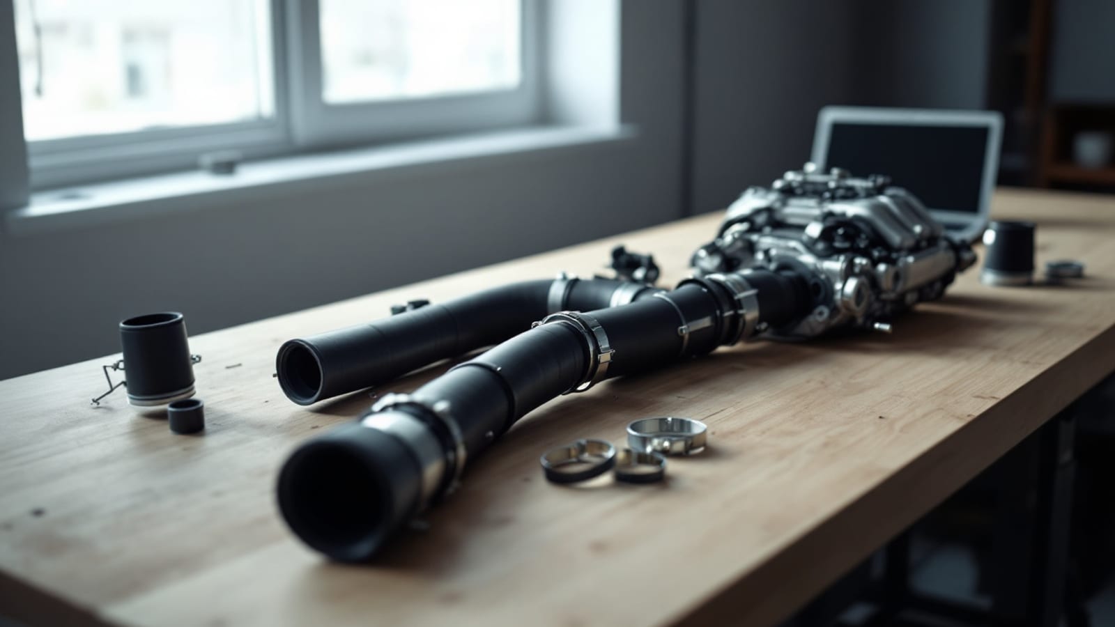
Every fuelling decision an engine control module makes begins with the same question: how much air just entered this cylinder? Everything downstream — injector pulse width, spark advance limits, whether the engine is safe at full load — inherits the answer. If the airflow estimate is wrong, nothing built on top of it can be right, no matter how carefully you tune it.
There are two ways to arrive at that estimate, and as of July 2026 most modern calibrations use both rather than one — which is precisely why the two fail in completely different ways and why people misdiagnose which one is at fault. Knowing which one your car is trusting at any given moment is the difference between fixing a problem and moving it somewhere else.
The two models
Mass airflow. A sensor sits in the intake tract and measures incoming air directly. The classic implementation is a heated element: air passing over it carries heat away, the current required to hold it at temperature tracks the mass of air flowing, and a transfer function converts that electrical signal into an airflow value. The calibration then computes fuel from a measured quantity.
Speed density. No airflow sensor at all. The calibration calculates airflow from manifold absolute pressure, intake air temperature, engine speed, and displacement, corrected by a volumetric efficiency table describing how effectively the engine fills its cylinders at each combination of speed and load. It is a prediction rather than a measurement.
One measures, one predicts. That distinction drives everything else.
| Mass airflow | Speed density | |
|---|---|---|
| Source of truth | A physical sensor reading | A model plus MAP and temperature |
| Adapts to weather and altitude | Automatically — it measures the real air | Through the temperature and pressure inputs |
| Sensitive to intake tract changes | Very — the sensor's calibration assumes a specific tube | Not at all |
| Sensitive to camshaft changes | Less so | Very — VE table must be re-tuned |
| Typical failure | Saturation at high flow, contamination, leaks after the sensor | A VE table that is wrong in cells you rarely visit |
| What breaks it | New intake, relocated sensor, dirt on the element | A cam swap, heads, forced induction |
| Diagnostic tell | Airflow trace flattening at high RPM | Trims fine in one region and wrong in another |
Most cars run both
The tidy either-or framing is largely historical. Modern calibrations commonly run a blended strategy — mass airflow as the primary source where the sensor is accurate, speed density as a fallback at the extremes of the range, during startup, and if the sensor faults out.
This has a consequence people discover the hard way. A car with an excellent MAF curve and a neglected VE table runs beautifully until it needs the fallback, then runs badly for reasons that appear random. You get an intermittent problem at cold start, or at very light throttle, or after a sensor fault clears, and none of it correlates with anything you changed.
If your platform blends, both models need to be right. Not one.
How each one lies to you
Mass airflow failure modes:
- Saturation. Airflow exceeds the sensor's range, the reading flattens, and the calibration under-fuels at maximum load. The log signature is unmistakable once you know it — airflow going horizontal while RPM keeps climbing, with air-fuel ratio going lean at the same moment. On a boosted engine this is genuinely dangerous.
- Contamination. Oil from an over-serviced filter, dust, or general grime on the sensing element changes its heat transfer, and it typically under-reports. The error is not constant across the flow range, which makes it look like a calibration problem.
- A leak downstream of the sensor. Air entering after the sensor is never measured, so the engine receives more air than the computer knows about and runs lean. No table change fixes a hole.
- A changed intake tract. The transfer function was characterised in a specific tube at a specific position. Move the sensor, change the tube diameter, or add a different filter and the same air produces a different signal.
Speed density failure modes:
- A VE table that does not describe your engine. A camshaft with more overlap, ported heads, or a different intake all change how well the engine breathes at each speed and load, and the factory VE table describes the factory combination.
- Errors hiding in cells you rarely visit. You tune at cruise and wide-open throttle, the car behaves, and then one day you hold an unusual load and the fuelling falls apart because that region was never corrected.
- Bad temperature or pressure input. The model is only as good as its inputs. A drifting intake air temperature sensor corrupts a VE calculation silently.
Telling them apart in a log
The diagnostic method is the same regardless of which model you are chasing: let the fuel trims tell you where the airflow estimate is wrong.
The computer computes fuel from its airflow estimate, then the oxygen sensor feedback corrects the result, and those corrections are recorded as short-term and long-term fuel trims. A consistently positive trim means the model under-estimated air. A consistently negative trim means it over-estimated. The pattern of where the trims are wrong identifies the culprit:
- Wrong everywhere by a similar amount — a global scaling error. Often injector data rather than airflow; see the injector data guide before touching the air model.
- Wrong at high flow only, with the airflow trace flattening — MAF saturation.
- Wrong at high flow only, airflow still climbing — transfer function error at the top of the curve.
- Wrong at idle and light load only — often a leak, or short-pulse injector behaviour, or a VE table that is wrong at low load.
- Wrong in scattered regions with no pattern — VE table cells that were never corrected.
- Fine in closed loop, wrong at wide-open throttle — you are in open loop and the model's error is no longer being masked by feedback. This is what a wideband exists to reveal.
The MAF and VE correction calculator turns those trim percentages into the corrections to apply, and the MAF curve reference covers reshaping a transfer function properly.
The order of operations
This is where most airflow work goes wrong, so it is worth stating explicitly.
- Rule out the mechanical. Intake leaks after the sensor, a dirty element, a loose clamp, a cracked hose. Every hour spent tuning around a leak is wasted the day it is fixed.
- Verify the inputs. Coolant and intake air temperature sensors reading correctly. A VE calculation is only as good as the temperature it uses.
- Confirm injector data. If injectors have been changed and the data is wrong, every airflow correction you make will be absorbing an injector error into the air model. This is the single most common way a good VE table gets corrupted.
- Correct VE first. It is the underlying model and the fallback path. Get it right across the range you actually drive.
- Then correct the MAF curve, if you run one.
- Re-verify both across a wider range than you tuned in.
Doing steps four and five in the reverse order is the classic error. Correcting a MAF curve on top of a wrong VE table gives you a car that works in the exact conditions you tuned in and nowhere else, and it makes the eventual VE correction much harder because you can no longer tell which model an error belongs to.
Our LS swap tuning process walks the same sequence in the context of a full build, and the MAF calibration page covers the tables involved.
When to change strategies deliberately
Sometimes the right answer is to change which model the car uses.
Moving to speed density makes sense when the intake tract is being reworked in ways that no MAF calibration will comfortably survive, or when a large camshaft makes the airflow signal unstable at idle and low load. You remove a sensor and a table from the problem, at the cost of needing a genuinely correct VE table across the whole range.
Keeping or adding mass airflow makes sense when conditions vary a lot — big swings in altitude, temperature, or fuel — because a measurement adapts where a model has to be told. It also gives you a real-time cross-check against the VE prediction, which is useful diagnostic redundancy.
Running both, blended, is what most factory calibrations do and is usually the right call on a street car. It costs you the work of maintaining two models and buys you graceful behaviour when either one is outside its comfort zone.
Whichever you choose, the speed density glossary entry and the engine ECU tuning guide cover the underlying mechanics if you want more depth.
The check that actually matters
Whichever model your car uses, one test tells you whether the airflow estimate is trustworthy: does delivered air-fuel ratio match commanded through a full pull?
If yes, your airflow model is describing the engine correctly under load, and you can move on to spark with confidence. If no, stop. Nothing you do to timing will fix a fuelling error, and advancing spark on an engine that is running leaner than commanded is how the expensive outcomes happen.
The datalog channels reference covers the channels to log, and the AFR and lambda calculator handles unit conversion if your wideband and your tables disagree on notation.
Where TuneVault fits
TuneVault reads your VCM Editor tables from screenshots — MAF transfer, VE, injector data, fuelling targets — and audits them against each other rather than one at a time, which is how airflow errors get found. It flags a transfer function that saturates below your expected peak airflow, VE cells that are implausible for the engine you described, and the injector mismatches that so often get mistaken for airflow problems.
After you flash, the datalog pass checks whether the model held up under real load: commanded against delivered air-fuel ratio, trims across the range, knock retard, and intake air temperature. See the datalog analysis page for what the check covers, or start a tune to see which of your two air models is the one telling the truth.
The bottom line
Mass airflow measures and speed density predicts, most modern cars use both, and each fails in a way the other does not. Learn to read the trim pattern — where the error lives tells you which model owns it — and fix things in order: mechanical first, inputs second, injector data third, VE fourth, MAF fifth. Then prove the whole thing with a pull where commanded and delivered air-fuel ratio agree. An honest air model is the foundation everything else in a calibration is built on, and it is worth the afternoon it takes to get right.
Frequently asked questions
What is the difference between MAF and speed density?
A mass airflow system measures incoming air directly with a sensor in the intake tract and uses that reading to calculate fuel. Speed density does not measure airflow at all — it calculates it from manifold pressure, intake air temperature, engine speed, and a volumetric efficiency table that describes how well the engine breathes. One measures and one predicts, and each fails in a different way.
Which air model is better for a modified engine?
Neither is universally better. Mass airflow adapts well to changing conditions because it measures what is actually happening, but it depends on the intake tract matching what the sensor was calibrated in. Speed density is immune to intake tract changes but depends entirely on a VE table that must be corrected for your camshaft and heads. Modified engines with wild cams often suit speed density; forced induction and variable conditions often suit mass airflow.
How do I know which model my ECU is using right now?
Many modern calibrations use both and blend between them, so the honest answer is often "both, depending on conditions." Log the airflow value and the manifold pressure together across a range of loads and watch which one the fuelling appears to follow. Failing that, the calibration itself contains the switching or blending logic, and reading it is more reliable than inferring from behaviour.
What is MAF saturation?
It is what happens when airflow exceeds the top of the sensor's measuring range. The reading flattens out and stops increasing even though real airflow is still climbing, so the calibration under-fuels at exactly the highest load. In a log it looks like an airflow trace going horizontal while RPM and boost continue rising, usually with air-fuel ratio going lean at the same instant. On boosted engines it is one of the most dangerous failure modes there is.
Do I need to tune the VE table if my car runs a MAF?
Usually yes, because most calibrations fall back to the VE model in some conditions — at startup, at very low or very high airflow, or when the mass airflow sensor is faulted out. A car with a good MAF curve and a bad VE table runs well until the moment it needs the fallback, then runs badly for reasons nobody can find. Sort both.
Can a dirty MAF sensor cause tuning problems?
Yes, and it produces one of the more confusing symptom sets because the error is not constant across the range. A contaminated sensing element typically under-reports airflow, so the computer adds fuel via trims to compensate, and the correction it needs differs at different flow rates. Before making any calibration change to a MAF curve, confirm the sensor is clean and the intake tract has no leaks after it.
Which should I correct first, the VE table or the MAF curve?
The VE table, then the MAF. VE is the underlying model of how the engine breathes and it is what the calibration falls back on. Correcting a MAF curve on top of a wrong VE table produces a car that behaves in the conditions you tuned in and misbehaves outside them, and it makes the second round of work harder because you cannot tell which model the error lives in.