Cam Phasing Tuning: What GM and Ford Variable Valve Timing Tables Actually Do
Variable valve timing is the table set most DIY tuners leave alone, and often the one with the most torque left in it. What cam phasing changes, why it breaks the air model, and how to adjust it without creating a misfire you cannot find.
By TuneVault
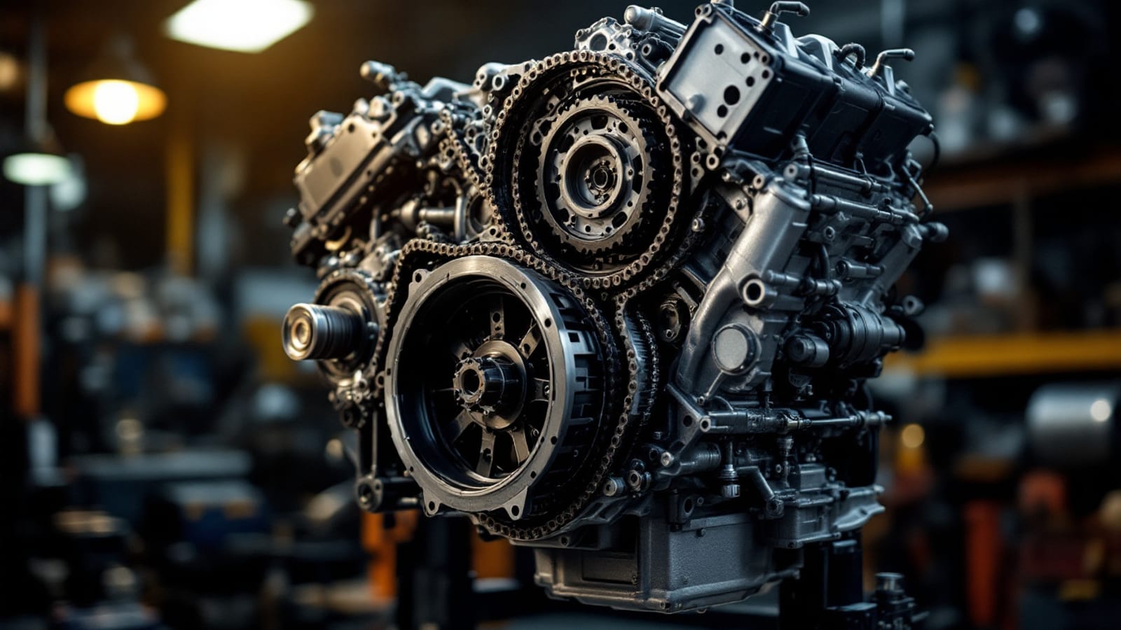
Variable valve timing is the part of a modern calibration most DIY tuners never open, partly because it looks intimidating and partly because there is far less forum lore about it than about spark and fuel. That is a shame, because on many engines the factory phasing schedule leaves meaningful torque on the table — and because a phasing change made carelessly is one of the fastest ways to create a driveability fault that is very hard to trace back to its cause.
As of September 2026 the table structures below apply across the GM and Ford applications HP Tuners supports. The names and the number of phasers vary; the physics does not.
What the hardware is doing
A camshaft phaser rotates the camshaft relative to the crankshaft while the engine runs. It does not change how far the valves lift or how long they stay open — those are fixed by the lobe profile. It changes when the lift event happens relative to the piston.
That single degree of freedom has several distinct effects:
Cylinder filling changes. Intake valve closing timing largely determines how much air actually stays in the cylinder once the piston starts back up. Close it early and you trap a smaller charge but at higher effective compression; close it late and at high engine speed the incoming charge's momentum keeps filling the cylinder past bottom dead centre. That is why the best intake timing for low-speed torque and the best for peak power are different, and why a fixed camshaft is always a compromise.
Overlap changes. Overlap is the window where intake and exhaust valves are open simultaneously. More overlap at part throttle leaves exhaust gas in the cylinder, which lowers combustion temperature and pumping losses — genuinely useful for efficiency and emissions. Too much and combustion becomes unstable, because there is not enough fresh charge to burn reliably.
Effective compression changes. Because intake valve closing sets how much charge is trapped, phasing directly affects the effective compression ratio, which in turn affects how much timing the engine will tolerate before knock. Move the cam and the safe spark advance for that cell moves with it.
That third point is the one that catches people. Phasing is not an isolated adjustment — it lands in the middle of the relationship between airflow, compression and knock.
Why phasing breaks the air model
This is the practical consequence that dominates everything else.
The volumetric efficiency table describes how well the engine fills its cylinders at each speed and load point. Cam phasing directly changes cylinder filling. So a VE table is only valid for the phasing schedule it was calibrated against, and changing that schedule invalidates the air model in exactly the cells you touched.
Some platforms handle this explicitly with a phase-aware airflow model that takes cam position as an input. Others carry a single VE table that implicitly assumes the stock schedule. Which one you have determines how much work a phasing change creates, and it is worth establishing before you start rather than discovering it through mysterious fuel trims.
The practical rule that follows: never change phasing and the air model in the same session. If you do, and the car improves, you will not know which change did it — and if it gets worse, you will not know which to undo.
The tables you will meet
| Table | What it sets | Typical fault when wrong | Where it shows |
|---|---|---|---|
| Intake cam target angle | Commanded intake phase by speed and load | Torque dip in a narrow RPM band | A repeatable flat spot mid-range |
| Exhaust cam target angle | Commanded exhaust phase, where independent | Excess overlap, unstable part-throttle burn | Light-load misfire or rough cruise |
| Phaser response limits | How fast the cam is allowed to move | Lag on tip-in, hesitation on throttle | Delay between pedal and pull |
| Phase authority by temperature | Whether phasing is allowed when cold | Poor cold driveability if enabled too early | Cold-engine roughness only |
| Cam position error diagnostics | Tolerance between commanded and actual | A code when the phaser cannot keep up | Fault set under fast transients |
| Idle phase target | Overlap at idle | Rough or hunting idle | Idle quality specifically |
Two of these deserve emphasis.
Phaser response limits are a mechanical constraint, not a preference. Phasers are driven by engine oil pressure, so they move slower when the oil is cold, thin, dirty or low. Commanding a large, fast phase change the hardware cannot deliver produces a position error, which produces a code, and at best produces a delayed response the driver feels as hesitation. If your car developed a lazy tip-in after a phasing change, this is usually the reason — and the underlying cause is frequently oil condition rather than calibration.
Idle phase target is where an over-enthusiastic overlap strategy shows up first. Idle is the lowest-airflow condition the engine sees, so it is least tolerant of trapped exhaust gas. An engine that idles poorly after phasing work usually wants less overlap at idle, which is a two-cell edit — and it interacts with everything covered in our guide to idle control tuning.
A working order
Step one: baseline the air model at stock phasing. Get fuel trims flat with the factory schedule in place. This is your reference, and without it nothing afterwards is measurable.
Step two: pick one region. Not the whole table. Choose the region where you actually want more — usually mid-range torque for a street car, or the top end for something that lives at high RPM — and change only that. A dozen cells is plenty.
Step three: change in small steps. A few degrees at a time. Phasing is more sensitive than most tables, and large moves change knock behaviour as well as airflow, which means you can be evaluating a timing problem while thinking you are evaluating a breathing one.
Step four: re-correct fuelling for that region. The VE correction workflow applies exactly as usual, but only for the cells you changed. Do not re-correct the whole table.
Step five: evaluate honestly. Torque, not feel. A dyno makes this trivial; without one, comparable pulls in the same gear from the same speed on the same day, comparing engine speed against time, is a reasonable substitute — provided you are comparing logs rather than impressions.
Step six: check the rest of the operating range. A phasing change that helps at 4,000 RPM under load can hurt at 1,500 RPM in traffic. Drive the car normally, at part throttle, cold and warm, before considering it settled.
The failure modes worth recognising
Light-load misfire that is not ignition. Excess overlap at low load traps enough exhaust gas that the mixture burns unreliably. People replace plugs, coils and wires while the cause sits in a table. The signature is that it occurs only at light load and disappears under any real throttle — if the engine is smooth when you ask it for something and rough when cruising, look at overlap before parts.
A mid-range flat spot that was not there before. Usually a phase target that is now wrong for one narrow band, often because the table was edited by dragging a region rather than shaping a curve. Phasing tables want smooth transitions; abrupt steps between adjacent cells create abrupt torque changes the driver feels as a hole.
Hesitation on tip-in. The phaser being commanded to move faster than oil pressure allows. Check oil level, grade and condition first. On a high-mileage engine this can be as much a maintenance finding as a tuning one.
Knock appearing where it never used to. Advancing the intake cam raises effective compression, so the timing that was safe before may not be now. This is the reason to change phasing and spark separately: knock retard that appears after a phasing change is a real signal, not noise, and it means the timing table needs revisiting for those cells.
Platform differences that actually matter
On many GM small-block applications a single phaser moves the one camshaft, so intake and exhaust events move together. That constrains what you can do — you cannot independently set overlap and intake closing — but it also halves the number of ways to make a mistake. The differences between LS and LT generations include meaningful changes to how phasing is implemented and how much authority the calibration has over it.
Many Ford modular engines phase intake and exhaust independently, giving genuine control over overlap as a separate variable from intake closing. That is more capability and more opportunity to create an unstable part-throttle condition. Work on the Coyote platform in particular should treat overlap at cruise as something to change cautiously and verify over a long drive rather than a short one.
The general rule is the same one that applies everywhere in tuning: read the tables in the file in front of you. A video about a superficially similar engine on the other platform can be actively misleading here.
And if you have fitted a fixed camshaft
Installing an aftermarket camshaft into a variable-timing engine changes the whole picture, because the lobe profile the phasing schedule was designed around no longer exists. The factory targets were chosen for the factory lobes; with more duration and more overlap built into the cam itself, the same phase angle produces substantially more overlap than the calibration expects.
This is why a cam swap frequently produces a rough idle that survives careful fuelling work — the overlap at the idle phase target is now beyond what the engine can burn stably. Reducing commanded overlap at idle and light load is often the missing step, and it is a common thread in rough idle after a camshaft swap.
Where TuneVault fits
Phasing is a good example of where a file review is worth more than another forum thread. The Copilot reads the cam phasing tables out of your VCM Editor file alongside the air model and the timing tables, and flags the combinations that predict a problem — an aggressive overlap schedule behind an aftermarket camshaft, phase targets that step abruptly between adjacent cells, or a VE table that clearly was not re-corrected after a phasing change. It is part of the same $39 guided tune, and it works from your actual file rather than a generic recommendation for your engine family.
The bottom line
Cam phasing changes cylinder filling, valve overlap and effective compression at once, which means it changes airflow, combustion stability and knock behaviour at once. That is what makes it powerful and what makes it easy to get wrong.
Baseline the air model first, change one region at a time in small steps, re-correct fuelling for only those cells, and verify at part throttle as carefully as at wide-open throttle. Treat a light-load misfire as an overlap symptom before an ignition one, and treat new knock as a real consequence of raised effective compression rather than a coincidence. Done in that order it is one of the more rewarding table sets in the file — done all at once it is the fault you spend a month failing to find.
Frequently asked questions
What does variable valve timing actually change?
It rotates the camshaft relative to the crankshaft, which shifts when the valves open and close without changing how far they lift or how long they stay open. Advancing the intake cam favours low-speed torque and cylinder filling; retarding it favours high-speed breathing. On engines with a single cam operating both valve sets, moving it also changes valve overlap, which is what allows the calibration to use trapped exhaust gas as an emissions and efficiency strategy at part throttle.
Is there real power in tuning the cam phasing tables?
Often yes, and more than people expect — factory phasing schedules are compromised for emissions, noise and driveability across conditions the enthusiast does not care about equally. But the gains come from finding the phase angle each load and speed point actually wants, which requires either a dyno or extremely disciplined datalogging. Copying someone else's table is the single worst way to approach it because the optimum depends on the whole airflow path.
Why did my fuel trims go strange after changing the cam phasing?
Because moving the cam changes cylinder filling, which changes airflow at every point you touched, which invalidates the volumetric efficiency data in exactly those cells. The air model was calibrated at one set of phase angles and is now being asked to describe a different engine. This is why phasing changes and VE table work have to be done in the right order rather than simultaneously.
Should I lock the cam at one angle for simplicity?
It is a legitimate simplification for a race engine that operates in a narrow band, and a poor choice for a street car. Locking the phaser gives up all the part-throttle efficiency, idle quality and low-speed torque the system was providing, in exchange for making the calibration easier. You are trading away the reason the hardware exists to avoid the work of tuning it.
Why does the engine misfire at light throttle after aggressive phasing?
Too much valve overlap at low load traps more exhaust gas in the cylinder than the mixture can reliably burn. The result is unstable combustion that shows up as a light-load misfire or a rough cruise, and it is often blamed on ignition components. Reduce overlap in the low-load region of the table and the misfire generally disappears without touching a spark plug.
Do the tables work the same on GM and Ford?
The principle is identical but the implementation differs. GM small-block V8 applications commonly use a single phaser affecting both valve events together, while many Ford modular engines phase intake and exhaust cams independently, which gives more control over overlap and more ways to get it wrong. Read the tables in your own file rather than assuming a video about the other platform applies.
What order do I tune phasing and the VE table in?
Get a stable baseline air model at the stock phasing schedule first. Then change phasing in a limited region, then re-correct the VE table for that region, then evaluate whether the change actually helped. Changing both at once means you cannot tell whether a torque improvement came from better breathing or from fuelling that happens to be closer to target.